ENRP20003 Engineering Research Project Implementation Report 1 Sample
Assignment Details
The sum of marks for all marking criteria mentioned below is 100 which will be scaled to 20 marks out of the final unit grade.
1. Format
a) The cover page should include:
Assignment title
Project title
Student details (name, student ID)
Name of advisor
Submission date
b) These elements exist:
Table of contents
List of Figures/Tables
Roman page numbers for the initial pages numerical page number from Introduction section
Heading Numbers
c) Figures and Tables have captions and reference (if required).
d) The assignment has been written with no grammar mistake and it reads well.
2. Results Presentation (Max 10 marks):
a) The results are presented in Figures, Tables, or diagrams as appropriate and interpreted clearly in the body of the text.
b) The relevant error and limitations of experimental/simulation/fieldwork/case study measurements should be identified and explained correctly.
3. Results Interpretation and Analysis (Max 15 marks)
a) Results are thoroughly and logically discussed.
b) Results are explained and justified in detail.
c) Results are linked with the literature data.
d) The analysis demonstrates a high level of independent thought and critical thinking.
e) Key findings of the research are presented and linked with the research question, aims and objectives.
4. Updated Project Schedule (Max score 5):
The project schedule (Gantt Chart) demonstrates the updated project implementation plan (based on the planning schedule).
5. Response to the Reviewers Feedback (Rebuttal Letter) (Max score 18):
a) All the comments and feedback on the planning report provided by reviewers and project advisor have been responded to.
b) A detailed table with the list of feedback and how and where the feedback has been addressed (using hyperlinks pointing to the location of changes).
6. Revised Chapter 1: Introduction (with Track Changes) (Max score 14):
The Introduction should include the following sub-sections:
a) Project introduction
b) Background information
c) Problem statement
d) Research hypothesis
e) Overview of existing research
f) Benefits/importance of the project
g) Scope and limitations, and relevant information.
All elements must be present in your introduction.
7. Revised Aims and Objectives (Max score 5)
a) Aim(s) clearly defines the overall purpose of the project.
b) Aim and objectives are realistic and attainable, considering the constraints in terms of time, resources, technical ability and supports.
c) Objectives are aligned with the project aim.
8. Literature Review (Track Changes) - (Max score 10)
a) Develop a mind map to demonstrate the overview of the literature review and introduce it briefly to the readers.
b) Literature should be critically analysed, evaluated and presented in a logical and coherent manner with comments showing an excellent ability to synthesise and abstract knowledge.
c) Different concepts/arguments around the topic of each keyword and the relationship between them are explained.
d) The quality of the cited articles is excellent/very good, and a proper referencing style (both in-text and reference lists) has been used.
e) A relevant methodology and research gaps have been identified.
9. Revised Chapter 3: Methodology (Track Changes) (Max score 15)
a) All the research tasks with sufficient details are articulated.
b) The overview of the project mind map is presented and explained clearly.
c) The methodology approaches articulated the detailed procedure for each step as shown in the flowchart.
d) The key investigating parameters are identified and presented.
e) Relevant theories and equations to identify the key parameters are explained.
f) The design of the experiment/s is presented and explained.
g) Model validation approach (for simulation projects) is presented and explained.
10. Plagiarism
a) Plagiarism is an academic misconduct. Ensure your thesis is original and properly cites sources. Check the Turnitin score and make necessary revisions before submission.
b) Make sure that there is no AI-generated content.
c) Do not use previously published work without proper referencing.
Solution
Chapter 1 Introduction
Background Information
Scientists are looking for alternative renewable energy sources that can reduce the effects of fossil fuel usage in response to the increasing global need for energy, constraints on the use of fossil fuels, and their damaging impact on the environment. Energy storage is one of the most critical study areas for academics and researchers to reduce the energy supply-demand mismatch,Specialized devices called solar thermal heat exchangers are made to move thermal energy from one fluid to another. Computational Fluid Dynamics (CFD)simulation of thermal behaviour in different heat exchangers using solar Power technology has attracted of attention from around the world in the last ten years. . Industries such as power generation, chemical processing, and HVAC rely on heat exchangers, where inefficiencies result in significant financial losses, operational downtime, and increased carbon emissions, making performance optimization critical (Congedo, Colangelo & Starace, 2012).
Queensland, Australia, is the perfect place to generate solar energy because of its tropical and subtropical environment. The state is one of the sunniest in the world, with high annual solar radiation levels, making it an ideal site for commercial and domestic solar energy harvesting. Through several programs and incentives, the Queensland government has been aggressively promoting solar energy, which has resulted in a notable rise in solar panel installations throughout the state (Queensland Government, 2021; Australian PV Institute, 2022). Optimizing heat exchanger efficiency aligns with Queensland’s renewable energy goals, as improved thermal performance supports the effective utilization of solar energy ,for university assignment help reducing dependency on conventional power sources.
Project Introduction
Computational fluid dynamics (CFD) simulation is a powerful tool for analysing and predicting fluid flow and heat transfer behaviour in systems such as heat exchangers. Using advanced computer techniques to solve complex mathematical equations, CFD simulations allow to visualise and understand how fluids move and transfer heat within heat exchangers, leading to more efficient and optimised designs. Heat exchangers are widely used in many industries such as power plants, chemical plants, HVAC systems, and automobile industry. Their main use is for the purposes of managing heat between two or more fluids in a way that maximizes energy transfer. However, heat exchanger’s design and operational condition dependent and resultant of which it’s thermal performance can be aptly characterized by inefficiencies as well as operational issues (Hou et al. 2017). This is a common problem in varrious industries, where it involve heavy power plants, as well as minor HVAC systems installed in homes. This is especially the case if the heat exchangers are operating in unfavourable conditions for example high temperatures, corrosive environments and or variable loads. The interfaces and the corresponding problems tend to occur more frequently and be more severe when the equipment is old and has not been adequately maintained.
Fouling is the deposition of undesired substances on the heat exchange surfaces and turned into a layer that reduces the possibility of heat transfer (M. 2011). Heat exchangers’ ineffective thermal performance can be attributed to such things as fouling (shown in Figure 1), design flaws, and the choice of materials. Flawed design practices include inadequate surface area for exchanging heat or poor fluid flow regime, which make the thermal performance poor. This way, the inadequate material selection can cause the thermal degradation or/and corrosion this deteriorating the heat exchanger performance. Numerical modelling is a significant tool in the analysis and the enhancement of the thermal characteristics of various heat exchanger flow fields. Cui et al. (2022) studied the heat transfer with Phase Change Material (PCM) in simple and complicated shapes with the aid of finned cylinder isotherm. They compared the results with actual and existing values of heat exchangers and thereby, stressed the need for accurate modelling.
.png)
Figure 1 Fouling in Heat Exchanger (Fryer 2021)
Due to the various underlying equations, numerical methods are the most reasonable methods of analysing the heat exchanger performance among all different mathematical methods. One easily falls into is the finite differences, employed by (Faden, 2019) in solving the enthalpy equation for the solidification of a flat plate. To justify the applicability of these methods, Shamsundar offered a detailed account of their usage while idealizing square geometries and proving their efficiency in modelling heat transfer processes. The numerical simulations were carried out by Faden et al. (2017) on a two-dimensional rectangular domain using energy equations for both solid and liquid phase and continuity, momentum equations and at interface. They analysed three phase change materials (PCMs): intermediate in paraffin (n-octadecanoyl) and metals (gallium and tin), the numerical solution procedure used to be SIMPLEC (semi-implicit method for pressure-linked equations consistent). It was compared to the data found in the literature, and differences were detected in the case of octadecanoyl, especially in the upper zone where melting of liquid became an essential factor.
Overview of Shell-and-Tube Heat Exchangers
Shell-and-tube heat exchangers are widely used in various industrial thermal systems because of such notable features as high pressure-temperature suitability as well as maximal mechanical stability and service reliability. Such fluid exchangers include tubes arranged in a shell as they enable the heat transfer of two fluids. One fluid moves through the tubes, while the other passes over the tubes, transferring heat through the walls of the tubes. The features of construction and configuration of these exchangers enable their application into chemical processing and petroleum refining, power generation and HVAC applications.
The main part of a shell-and-tube heat exchanger is the shell, the tube bundle, the tube sheets, the baffles, the end covers and the nozzles. The shell often is cylindrical and surrounds the tube bundle which is a series of tubes through which the fluid passes. Tube sheets are used at both ends of the shell to support the tubes and gain a tight seal. Tubes are arranged in such a manner that baffles which are mounted on the inner periphery of the shell assist to guide the fluid within the shell across the tubes more than once to create turbulence and improve heat transfer. Heads are situated at each end of the shell and may be of any type as fixed heads, or floating heads or may comprise of U-tubes depending on maintenance aspects and thermal expansion. Nozzles are used as the inlet and outlet streams for both the shell-side and tube-side fluids for better flow distribution control as well as to minimize pressure losses.
.png)
Figure 2 Shell and Tube Heat Exchanger, (Arveng 2015)
In shell-and-tube heat exchangers, heat flows from one body to another through the shell-and-tube is through conduction and convection. Heat transfer is carried out by conduction at the walls and tube and the shell, and convection between the fluids and their contacted surfaces. The overall heat transfer coefficient which incorporates the conductivity and convection coefficients and the fouling coefficients to specify an efficiency of heat exchange decide the efficiency of the heat exchanger. There are many aspects which must be considered to obtain an ideal shell-and-tube heat exchanger: the chosen type of the heat exchanger material, the type of tube layout, the type of the baffles, the flow arrangements by which the fluids can flow across the heat exchanger and the problem of fouling.
The selection of materials used in the designing of heat exchangers is very significant towards the unyielding and reliable performance. Stainless steel (SS304) and copper are preferred most of the time because of their good thermal conductivity, resistance to corrosion, and strength. The selection of the material is determined by the corrosiveness of the initially used fluids and their operating temperatures. Tube layout and pattern like triangular or square pitching influence the flow pattern and heat transfer characteristics. For example, in the case of a triangular pitch it tends to have higher heat transfer coefficients but at the same time it tends to present a higher pressure drop than the one presented by the square pitch (Perera et al., 2023). The type of baffle, the spacing of the baffle and the cut or the pattern in which it is made determines the shell side fluid flow and in so doing increases turbulence and heat transfer but also increases pressure drop (EPCM Holdings, 2020). Various flow configurations which include counterflow, parallel flow, and crossflow also affect thermal efficiency the most, with counter flow being the most efficient.
Shell-and-tube heat exchangers are used in different industries since they are versatile and quite efficient in their performance. In chemical processing, they are employed for stream heating and cooling of technical processes. In petroleum refining, they use in condensing, heating as well as cooling of hydrocarbons. Applications of these exchangers are in the power generation industry in areas of steam condensers and feed water heaters While HVAC industries use them in large scale heating and cooling. Used processes such as pasteurization and sterilization the food and beverage industry use Shell and Tube Heat exchangers (Edreis & Petrov, 2020).
Nonetheless, the shell-and-tube heat exchangers possess some problems like fouling, pressure drop, and thermal stress. Heat transfer is adversely affected by fouling, which entails the formation of deposits on heat transfer surfaces. Efficient and proper control of fouling involves cleaning and maintenance of the contacts, hence, needs to be done often. The pressure drop due to the flow resistance increases with the necessity for proper design with respect to accomplish great heat transfer rates and low resistance. Thermal stress implies that some of the parts in the system will expand and others will contract, and this effect can lead to mechanical failure if the affects are not controlled.
Relevance
Behavior related to geometric designs of heat exchangers is critically important since these systems affect the efficiency of numerous processes in industries research on the thermal behavior related to geometric designs of heat exchangers is critically important since these systems affect the efficiency of numerous industries' processes. Ideally, heat exchangers would work at their best, and introduce improved dissipation of heat, less power use, and thermal management regardless of the state of operations. Such would lead to decreased expenditure on operations, increased efficiency of thermal control systems, increased efficiency of thermal control systems equipment working life, and improved thermal control system efficiency.
Heat exchangers’ performance is affected by some thermal inefficiencies, which are considered challenging. Lack of efficiency means more power consumption, as the structures work harder to transfer the required heat. The problem with the former isn’t only that it increases operating costs. but is also a factor for higher emission of greenhouse gases, hence compounding environmental issues. Further, temperature distribution non-uniformity may lead to localized thermal hot-spot generation, which in turn can lead to equipment failure and system failure, as well as increased levels of maintenance.
Solving this problem has the following reasons. Improvement in the effectiveness coefficient in heat exchangers would be equally expensive but would profoundly impact the cost and the environment. Better thermal control also would increase equipment reliability and service life, meaning less equipment failure and maintenance costs, precisely in fields were controlling or maintaining temperatures are critical to operations, as in power generation, and chemical processing, solving these inefficiencies would improve product quality and process consistency.
The lack of such problems would be a valuable outcome. This is because industries would cut their expenses, especially on energy, enhancing improved profit margins. That would contribute to the efforts to reduce the economic impact on the environment. Improving equipment reliability and performance would mean raising productivity or operation efficiency. Also, further developments in heat exchanger technology that are consequent of resolving these problems might be expanded to other fields as enhanced performance in one sector stimulates similar advancements in other industries
Problem Definition
The thermal efficiency of shell-and-tube heat exchangers, particularly those constructed from stainless steel (SS304) and copper, is frequently hindered by a range of design complexities and operational inefficiencies. These issues primarily arise from fouling—where unwanted materials accumulate on the heat exchanger surfaces—and suboptimal geometric configurations that result in inefficient fluid flow and heat transfer. Such inefficiencies lead to increased energy consumption, uneven temperature distribution, localized hotspots, and accelerated equipment degradation. In stainless steel (SS304) and copper heat exchangers, fouling significantly impairs heat transfer efficiency, which in turn escalates operational costs and energy waste. Furthermore, the design factors—such as tube arrangement, size, and baffle configuration—often result in suboptimal fluid dynamics, exacerbating the reduction in thermal efficiency.
This study aims to explore and implement solutions, focusing on optimizing the design and operation of shell-and-tube heat exchangers to improve their thermal efficiency. By integrating nanofluids into the simulation process, this research seeks to addressing the critical issues of fouling, design inefficiencies, and fluid thermal performance in heat exchangers.
Aim
Recent advancements in heat transfer fluids have introduced nanofluids—suspensions of nanoparticles in a base fluid such as water, ethylene glycol, or oil—as a potential solution to enhance thermal performance. Nanofluids, such as Al2O3–H2O, SiO2–H2O, and TiO2–H2O, have demonstrated improved thermal conductivity and heat transfer coefficients compared to traditional fluids. . Research indicates that these advanced fluids can improve heat transfer efficiency by up to 20% compared to conventional fluids (Wajahat Ahmed Khan et al., 2024). The inclusion of nanoparticles in the base fluid increases the overall thermal conductivity, potentially addressing some of the heat transfer limitations observed with conventional fluids. The addition of these nanoparticles can mitigate the impact of fouling and enhance the overall heat transfer efficiency of shell-and-tube heat exchangers. Addressing these inefficiencies is essential for improving the overall performance of shell-and-tube heat exchangers. Effective solutions could lead to substantial energy savings, reduced operational costs, and a lower environmental impact. Enhancing thermal efficiency can also extend the operational lifespan of these heat exchangers, reducing maintenance and replacement needs, and thereby lowering maintenance costs over time.To investigate the impact of nanofluids (Al2O3–H2O, SiO2–H2O, and TiO2–H2O) on the thermal performance of shell-and-tube heat exchangers, and to evaluate how different baffle arrangements affect heat transfer efficiency and pressure drop.
Objectives
1. To compare the thermal conductivity and heat transfer performance of shell-and-tube heat exchangers using different nanofluids (Al?O?–H?O, SiO?–H?O, TiO?–H?O) under various operating conditions.
o This involves evaluating how the inclusion of nanoparticles affects the heat transfer coefficient and overall thermal performance of the heat exchangers. The study will measure and compare the temperature differences, pressure drops, and effectiveness when using each type of nanofluid.
2. To analyse the effects of various baffle arrangements, including baffle type (helical vs. double segmental), baffle angle (5°, 6°, 7°, 15°, 30°, 45°), and baffle distance (30 mm, 60 mm, 90 mm), on the heat transfer efficiency and pressure drop in heat exchangers using nanofluids.
o This objective focuses on understanding how baffle design modifications influence heat exchangers' performance when nanofluids are used. The analysis will consider factors such as temperature distribution, pressure loss, and overall effectiveness.
3. To develop and validate a Computational Fluid Dynamics (CFD) model for simulating the performance of shell-and-tube heat exchangers with different nanofluids and baffle configurations.
o This includes creating a CFD model that accurately represents heat exchangers' thermal and fluid dynamics using Al?O?–H?O, SiO?–H?O, and TiO?–H?O nanofluids. The model will be validated against experimental data to ensure its reliability in predicting the effects of nanofluids and baffle arrangements on heat transfer performance.
Research Questions
o How do the thermal conductivity and heat transfer performance of shell-and-tube heat exchangers using Al?O?–H?O, SiO?–H?O, and TiO?–H?O nanofluids compare, and what are the effects of these nanofluids on temperature differences, pressure drops, and overall heat exchanger effectiveness?
o What are the impacts of different baffle arrangements—such as baffle type (helical vs. double segmental), baffle angle (5°, 6°, 7°, 15°, 30°, 45°), and baffle distance (30 mm, 60 mm, 90 mm)—on the heat transfer efficiency and pressure drop in shell-and-tube heat exchangers when using nanofluids?
o How accurately can a Computational Fluid Dynamics (CFD) model predict the thermal performance and pressure drop of shell-and-tube heat exchangers incorporating Al?O?–H?O, SiO?–H?O, and TiO?–H?O nanofluids with various baffle configurations, and how does the model validation compare with experimental data?
Project Scope
Inclusions
• Design Configuration Evaluation: Evaluating different tube arrangements, baffle spacings, working fluid and configurations to determine the most efficient geometry.
• CFD Model Development and Validation: Developing and validating a CFD model to predict thermal performance under various operational conditions.
• Reporting and Documentation: Compiling findings, methodologies, and recommendations into a comprehensive report.
Exclusions
• Non-Shell-and-Tube Heat Exchangers: Analysis and optimization of heat exchangers other than shell-and-tube types.
• Manufacturing Process Optimization: Improvements to the manufacturing processes for SS304 and copper heat exchangers.
• Cost-Benefit Analysis: Detailed financial analysis of cost savings and ROI from the proposed design modifications.
• Material Cost Analysis: In-depth analysis of the cost differences between SS304, copper, and alternative materials.
• Implementation of Proposed Modifications: Actual modification and implementation of changes in industrial heat exchangers.
Project Outcomes and Deliverables
Outcomes
1. Improved Thermal Efficiency: Achieving enhanced heat transfer efficiency shell-and-tube heat exchangers through optimized design and operational parameters.
2. Validated Computational Model: Developing a reliable CFD model that accurately predicts the thermal performance of heat exchangers under various operational conditions.
Deliverables
1. Comprehensive Report: A detailed document presenting the impact of nanofluids on heat transfer efficiency, including CFD data. It will include evaluating different tube arrangements, baffle spacings, and configurations and identifying the most efficient design geometries.
Chapter 2 Literature Review
Introduction
Heat exchangers are widely used in many industries, to transfer heat from one fluid to another to enhance efficiency and minimise energy waste. They are used to transfer heat from one fluid to another to enhance efficiency and minimise energy waste. However, modern and common shell-and-tube heat exchangers being developed using of stainless steel and copper that have various of challenges that affect their thermal efficiency. Such challenges are fouling, which occurs where unwanted deposits form on the surfaces of heat exchangers and irregular disposition of the tubes and baffles. These problems affect heat transfer; also affect energy consumption, the cost of operations, and energy consumption. It lead to the quick deterioration of the equipment.
The solution of to these issues is crucial for industries that require effective thermal management to preserve their production rate and decrease emissions. Improvement of heat exchanger design and practical implementation leads to an increase in thermal efficiency factors, and consequently, energy-saving and reduced maintenance expenses.. This project will seek to find out and come up with measures that may act as the solution to these inefficiencies, thus helping in the provision of a coherent industrial system that is sustainable and cheaper in the long run.
Articulation of Literature Findings
Heat Transfer Coefficient Limitations: Channel Dimensions and Heat Transfer Fluids
One of the main challenges that affect the heat transfer coefficient with respect to heat exchangers is the influence of a decrease in channel sizes as a means of enhancing the heat transfer area; this tends to increase pressure drop considerably (Kücük, Ünverdi and Senan Y?lmaz, 2019). For example, such a situation is inherent in microchannel heat exchangers in which the channels are designed to be as small as possible to create heat transfer surface area. The concept behind this design lies in the knowledge that channels, if made small, would improve the surface area to volume ratio and so improve convection. Nonetheless, it has been realized that as the dimensions of the channel reduce, the resistance to flow is enhanced and thereby, the pressure differences across the heat exchanger also escalate (Rajalingam A and Chakraborty, 2023). Such a situation leads to more pressure drop, and so more energy is required to maintain the flow rate, thus making the system less efficient. Research has indicated that there is a great potential for microchannel designs to boost heat transfer rates by about 50%. However, pressure drop are incurred up to three or four times those of conventional heat exchangers .
The relationship between channel dimensions and pressure drop can be mathematically described by the Darcy-Weisbach equation, which states:

where:
• ΔP is the pressure drop,
• f is the friction factor,
• L is the length of the channel,
• D is the hydraulic diameter of the channel,
• ρ is the fluid density, and
• V is the flow velocity.
By reducing the hydraulic diameter of the channel, the pressure drop ΔP increases very sharply, more so when the flow is turbulent, as is generally observed in many microchannels. This equation proves that certain pressures need to be dropped to attain higher heat transfer rates in a heat exchanger design.
Another factor affecting the heat transfer coefficients is the working fluids used in the heat exchange process; their thermal conductivity is the main factor. Compared with organic heat carriers such as oil and ethylene glycol, water heat transfer fluids are selected more frequently because of their advantages, including availability,low costand moderate hazards. However, these fluids have relatively low thermal conductivities, which restrict the amount of heat which limits the amount of heat that these fluids can transfer. For example, while thermal conductivity of the water is around 0. 25 W/m·K and propane is about 0. 25 W/mK, and oil is even much lower and may be graded at about 0. 13 W/m·K (Mohammad Hemmat Esfe, et al., 2016). These values are much lower than those of metals such as copper at about 400 W/m·K or Aluminium at about 237 W/mK. This shows that these fluids are, in most cases, the bottleneck for heat exchangers.
The drawbacks of traditional heat transfer fluids can be partly alleviated by raising the of fluid's flow rate. Still, the consequence is that energy costs rise, and the equipment becomes larger and more costly. Nanofluids, which are suspensions of nanoparticles in base fluids such as water or ethylene glycol, have been investigated in the last few years as a means of increasing the thermal conductivity of heat transfer fluids. Nanofluids have shown promise in increasing heat transfer rates by up to 20% compared to traditional fluids (Wajahat Ahmed Khan et al., 2024). The enhancement in thermal conductivity can be modelled using the Maxwell-Garnett equation, which describes the effective thermal conductivity of a composite material:
.png)
where:
k_eff is the effective thermal conductivity of the nanofluid,
k_f is the thermal conductivity of the base fluid,
k_p is the thermal conductivity of the nanoparticles, and
? is the volume fraction of the nanoparticles.
While nanofluids show potential for overcoming the limitations of traditional heat transfer fluids, their application is still in the experimental stage. Issues such as stability, compatibility with materials, and cost-effectiveness have yet to be fully resolved.
Enhancement of Thermal Conductivity through Nanofluids
The incorporation of nanoparticles into base fluids has emerged as a significant advancement in enhancing the thermal conductivity of heat transfer fluids. This approach leverages fluids solid metal particles' high thermal conductivity to improve conventional fluids overall heat transfer performance. Several studies have contributed to understanding and optimizing this technology, each offering unique insights into the effects of nanofluids on heat transfer.
.png)
.png)
Table 1 Published work for different Nanofluids and their findings
Arsana et al. (2021) focused on the review of the thermal conductivity improvement by dispersing nano-scale particles with sizes below 100 nm spread in a base fluid as nanofluid technology. Their research was to determine how such nanoparticles with high thermal conductivity could enhance the thermal conductivity of the base fluid. The study from placing a qualitative emphasis on the fact that nanoparticles have a very small size and very high thermal conductivity, which has a very positive effect on the heat transfer capacity of the base fluid. The test procedures required employing nanofluids with the use of nanoparticles in liquids, for example, water and ethylene glycol with copper, alumina and silver, among others. The investigated research proved that the enhancement of thermal conductivity was achieved due to the addition of these nanoparticles when compared with the base fluids. This is so because the nanoparticles introduce new pathways for heat conduction and, therefore, enhance thermal conduction. The outcomes focused on the fact that by increasing the volume fraction of nanoparticles in the nanofluids, their thermal conductivity may be Boosted by more than 30% compared to that of the base fluid and reveal the promotion potential of nanofluids in advanced heat transfer applications.
In an experimental study, Farajollahi, Etemad, and Hojjat (2021) investigated the effect of nanofluids on shell-and-tube heat exchangers. They particularly focused their study on some of the nanoparticles, such as Al2O3 (alumina) and TiO2 (titanium dioxide) dissolved in water at a turbulent flow system. Among all the parameters, the Peclet number, volume concentration of nanoparticles and type of nanoparticles were taken into considered in the course of the study. This move was followed by the evaluation of the results which showed improved heat transfer performance with the use of nanoparticles. It was, therefore, observed that the HTC value was higher in the nanofluid than in the base fluid at the same Peclet number. This enhancement was attributed to the increased enhanced thermal conductivity qualified by nanoparticles and enhanced flow dynamics. The study also identified that work done on the volume concentration had made a clear upward trend in enhancing the heat transfer rates and that nanofluid comprising Al2O3in water outperformed TiO2in water nanofluid.
.png)
Table 2 Thermos physical properties of Nano fluids at volume fraction of 2%, Image Source: Bhanuteja and Azad (2013)
In a study by Mapa and Mazhar (2018), they focused on using nanofluids on the mini heat exchanger, where they used water and nanoparticles of different concentrations. Their experiments utilised nanofluid with a concentration of 0. 01% and 0.02% volume and comparing with performance of normal water. Little concentrations of the nanoparticles are used in these cases, and the study was undertaken to establish the impact of the low concentrations on heat transfer rates. These studies affirmed that heat transfer performance in nanofluids is improved. As nanoparticles were present in the base fluid, the thickness of the thermal boundary layer was lesser and thereby helped in improving the heat exchange between the fluid and the heat exchanger surface. Reducing the thickness of the boundary layer, increases the rate of thermal exchange and therewith improves the coefficient of heat transfer. This study pointed out that heat transfer improvement could have a larger function even if the nanoparticle concentration is very low, which indicated the feasibility of the application of nanofluids for practical use.
Masuda et al. (2014) studied the enhancement of the thermal conductivity of fluids with the help of nanoparticles. Their studies were confined to the increase in the thermal conductivity of base fluids by the addition of nanoparticles in the range of 1–5% in volume. The research proved that the thermal conductivity of the suspension may rise to 20% by the incorporation of nanoparticles. According to Masuda et al. (2014) thermal conductivity of base fluids increased with nanoparticles like alumina and copper. Likewise, Xuan and Li also reported that the thermal enhancements were directly proportional to the amount of the nanoparticles, though noticeable enhancements have been obtained even at low concentrations. These studies highlighted the benefits on nanofluids on thermal properties more than traditional fluids, which is essential for thermal applications.
Choi et al. (2021) recently came across meaningful research about how nanoparticle addition affects the thermal conductivity of traditional heat transfer liquids. Their research proved that when volume was added below 1% of nanoparticles, the effective thermal conductivity of the base fluids could be increased by nearly a factor of 2. This emphasized thermal conductivities of improvement capability of even a small number of nanoparticles. Numerous studies were carried out based on the research results of this study, and a premise ground for the analysis of the nanofluid heat transfer was provided. This observed enhancement of the thermal conductivity helped pave a the way to design new heat transfer fluids with still improved thermal characteristics.
Effect of Baffle Arrangement on Heat Exchangers
Baffles are crucial in shell-and-tube heat exchangers, significantly impacting thermal performance and fluid dynamics. The optimization of baffle arrangements—encompassing baffle type, angle, and distance—can greatly influence the efficiency of heat exchangers.CFD ) has become an essential tool for analysing and optimizing these configurations because it provides detailed insights into fluid flow and thermal behaviour. This review focuses on the effect of baffle arrangements on heat exchanger performance, emphasizing CFD analysis, equations, and experimental validation. The type of baffle used in a heat exchanger determines the flow pattern and heat transfer characteristics. Baffle types include segmental, helical, and disc-and-doughnut configurations. Each type affects the fluid dynamics and heat transfer differently.
Segmental baffles are commonly used for their simplicity and effectiveness in creating crossflow patterns that enhance heat transfer. However, they can also lead to increased pressure drop due to flow obstruction. The effectiveness of segmental baffles can be assessed using the following relationship for pressure drop (ΔP) and temperature difference (ΔT):
.png)
Helical baffles induce a spiral flow pattern that can reduce pressure drop while maintaining high heat transfer rates. This configuration helps reduce the formation of dead zones and enhance fluid mixing. The heat transfer coefficient (h) for helical baffles can be expressed as:
![]()
where Q is the heat transfer rate, A is the heat transfer area, and ΔT is the temperature difference between the fluids.
The baffle angle influences the flow pattern and heat transfer performance. Smaller baffle angles generally reduce flow disturbance but can also decrease heat transfer efficiency due to lower turbulence levels. The baffle angle (θ) affects the heat exchanger effectiveness (ε) as follows:
![]()
For different baffle angles, such as 5°, 6°, and 7°, the temperature difference (ΔT) and effectiveness (ε) are analysed by Arsana and Wahyuono (2021). Results suggest that as the baffle angle increases, the heat exchanger performance decreases due to increased flow resistance and reduced turbulence.
The distance between baffles or baffle spacing, is crucial in determining the thermal performance and pressure drop. Shorter baffle distances typically lead to higher heat transfer rates but can increase pressure drop. Conversely, more considerable baffle distances reduce pressure drop but may lower heat transfer efficiency. The impact of baffle distance (d) on heat exchanger performance can be analysed using the Darcy-Weisbach equation
The effectiveness (ε) of heat exchangers with varying baffle distances can be evaluated by:
where C_min represents the minimum heat capacity rate, T_(h,in) is the hot fluid inlet temperature, T_(c,in) is the cold fluid inlet temperature, and T_(c,out) is the cold fluid outlet temperature.
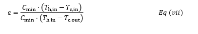
The table summarising various baffle modifications in heat exchangers reveals significant insights into their effects on performance parameters such as temperature difference (ΔT), pressure drop (ΔP), and effectiveness (ε).
Table 3 CFD Analysis Results, Image Source: Arsana and Wahyuono (2021)
One of the most significant factors that define the performance of a heat exchanger is the type of baffles to be used. For example, helical baffles with baffle spacing of 164mm develop 17.7°C temperature difference and a pressure drop of 7.36 kPa, thereby resulting in an effectiveness of 0. 35. This configuration gives a reasonable heat transfer rate, and, at the same time, a low pressure drop. Same as above, double segmental baffles of the distance of 100 mm cause a temperature difference of 14. 4 ° C and a pressure drop of 14.48 kPamore than helical type.
Heat exchangers are highly sensitive to the setting of helical baffles particularly the resulting angle. At the 6° angle, the baffles provide the maximum difference in temperature of 25.4°C, however there is a severe pressure loss 123. 9 kPa and an effectiveness of 0.50. FoWhen the baffle angle is adjusted to 7°, then the above temperature difference increases to 21. 4°C and a pressure decrease of 88. 4 kPa, and an efficacy of 0. 45. Although not as high as of the 6° configuration, the performance is sufficient all the same. Increasing the angle even more up to 8° gives a temperature difference of 15.7°C 70.7kPa.. The most effective were found to be operating at pressures of 7 kPa with a low effectiveness of 0.32. This suggests that while high angles decreases pressure drop, at the same time decreases heat transfer rates.
Both double segmental baffles also depend on angle for their performance. From which it follows that the temperature difference is 24 degrees, when the angle is 15 °C and strong pressure drop equals 183. 4 kPa, it is claimed to have a effectiveness of 0. 48. This indicates that the baffle angle increases the heat transfer rate, while increasing the pressure drop at the same time. When the angle gets larger to be 30°, the variation in the temperatures reduces to 13.7°C although this is a little below the peak value.This indicates a trade-off between heat transfer performance and increased pressure drop. At a 45° angle, the temperature difference further decreases to 4.7°C, with a pressure drop of 178.1 kPa and a notably low effectiveness of 0.09. This configuration shows a significant reduction in both heat transfer and effectiveness, highlighting the diminishing effect of higher baffle angles.
Baffle distance in disc and doughnut baffles markedly influences performance outcomes. A baffle distance of 0.3 cm results in the highest temperature difference of 48.0°C and the lowest pressure drop of 1.95 kPa, with an effectiveness of 0.93. This configuration offers exceptional heat transfer performance with minimal pressure loss. Increasing the baffle distance to 0.6 cm reduces the temperature difference to 8.0°C and increases the pressure drop to 2.98 kPa, leading to an effectiveness of 0.20. This suggests a reduction in performance as the distance increases. A further increase to 0.9 cm results in a temperature difference of 9.0°C, a pressure drop of 2.21 kPa, and the lowest effectiveness of 0.15. This further confirms that more considerable baffle distances lead to lower heat transfer performance and effectiveness, emphasising the importance of optimising baffle spacing for efficient heat exchanger design.
Critical Evaluation of the Findings
The literature analysis regarding the thermal efficiency and enhancement in shell-and-tube heat exchangers, paying attention to SS304 and copper-based heat exchangers, provides a list of the factors affecting heat exchanger performance. These studies provide significant information, but some issues need to be highlighted and discussed to further the research.
1. Heat Transfer Coefficient Limitations: Channel Dimensions and Heat Transfer Fluids
However, the trending thinning of channel dimensions to enable improved heat transfer surface is a mixed blessing. Despite theoretically raising the power of surface area to volume ratio and enhancing heat transfer rates probabilities of achieving constantly raising the power of surface area to volume ratio and improving heat transfer rates, probabilities of achieving always run into a problem of high-pressure drops. This trade-off, stressed in the Kücük, Ünverdi, and Senan Y?lmaz (2019), and and Rajalingam and Chakraborty (2023) research, shows that the design of heat exchangers is optimisation problem. These problems are worse off because of the use of conventional fluids that possess low thermal conductivity, according to Mohammad Hemmat Esfe et al., (2016). The nanofluids as a solution have been discussed and are still in the experimental stage, and the problems of stability and cost remain. From this, it can be deduced that while nanofluids hold a lot of promise, therefore, it can be deduced that while nanofluids hold a lot of promise, their use in industrial processes remains to be seen. That is why it is necessary to investigate the mentioned practical concerns in the following research works for using the potential of nanofluid technology in practice.
2. The second approach of promoting thermal conductivity is of Nanofluids.
The reviewed works on nanofluids can be regarded as convincing evidence that these new-generation heat transfer agents can increase the thermal conductivity and, therefore, the efficiency of heat transfer. Arsana et al. (2021) and Farajollahi, Etemad, and Hojjat (2021) find that the heat transfer performance is enhanced when nanoparticles are introduced into the base fluids. Nevertheless, these outcomes should be discussed in the light of their reproducibility and manufacturing relevance. In the experiments that are conducted, the environment may be artificially developed in the lab which may not be very much close to the operation environment. Also, there is a lack of generality due to the focus on specific nanoparticle types and base fluids. Experimental research endeavours need to include even more nanoparticles, base fluids, and operational conditions to determine the general viability of nanofluids.
3. Effect of Baffle Arrangement on Heat Exchangers
The literature review shows that the ability of baffle design to modify the performance of this heat exchanger has been well established, with a CFD analysis that describes the consequences of the variation of the type of baffle, angle, and spacing between adjacent baffles. Arsana and Wahyuono's (2021) works revealed that the combination of the helical baffle provides the best features of each type since it provides excellent heat transfer while keeping pressure losses reasonable. However, the variability in performance based on baffle configuration highlights a critical challenge: it can be summed up by the saying, ‘The only thing that suits everyone is a suit.’ One must realise that the efficiency of a particular baffle arrangement depends on the application and the operating conditions. This leads to the idea that for better solutions to various heat exchanger problems that may occur in the industrial practice, new, more flexible and individual approaches to their design should be used. In addition, the protective strategies presented herein utilize CFD simulations, which though useful for gaining insight into the matter, should be accompanied by the experimental data for the purpose of verifying the model’s confidence and application of real-world outcomes.
This being the case, the following areas still need research in advancing heat exchanger design and optimisation. First, the incorporation of nanofluids into the conventional heat exchangers raises some practical issues that have not been solved. Other things like stability over long periods, compatibility with the materials, and the cost of production are still matters of concern regarding their usage. Second, although the optimisation of baffle arrangements has been studied extensively, new and more efficient design models must be introduced, especially within the frameworks that may be adapted to the necessities of certain specific industries. Finally, since these technologies are implemented in facilities or are products that people frequently use, the effects that the applications of these technologies have of these technologies on the environment, its energy needs, and resources must be a focus of another research. The application of sustainable materials and energy resources, for example, the utilization of solar power in CFD and heat exchangers, may also be used as the direction for further research.
Discussion
The calculations of the literature study reveal the multiple interfacial links between the design parameters of shell-and-tube heat exchangers and their thermal performance and pressure drop. From the literature, one understands that the traditional heat exchanger designs present some inherent problems, especially with conventional heat transfer fluids such as water and ethylene glycol. On the other hand, these fluids are popular with nasty low thermal conductivities that limit the heat transfer rates of the exchangers. The integration of nanofluids appears to be a viable answer to the problem because of better thermal conductivity and high heat transfer rates. Nonetheless, the use of nanofluids is yet in its infancy and problems such as stability, cost, and material suit are still challenging to solve before that new type of fluids can find a large diffusion.
When looking strictly at baffle arrangement, the literature review findings reveal that baffle type, angle, and spacing directly affect heat transfer and pressure drop. Certain types of baffles, such as spiral ones, seem to offer better performance, at least in terms of heat transfer and pressure drop and therefore are worth considering in comparison with segmental ones. These are also confirmed by the CFD analyses done in various works, which show that improvements in baffle arrangements can significantly affect heat exchanger efficiency. But the studies also point to the fact that there is always a concern that power; using high baffle angles or small baffle distances would enhance heat transfer and, at the same time, would imply a high-pressure drop across the baffle, whereby more energy would be needed to circulate the fluids.
When focusing on identifying the singular ‘best’ solution, the research identifies that combining the best baffle arrangements with nanofluids could be the most effective in driving the most significant percentage increases in thermal efficiency accompanied by low deteriorations in pressure drops. This approach leverages the advantages of both technological advancements: The improvement in thermal properties of nanofluids and the best flow behaviour in the presence of well-designed baffles. Nevertheless, practical application would mean overcoming the existing drawbacks of nanofluids and optimising the geometry of baffles to provide the a level of efficiency with minimal energy consumption.
Conclusion
The challenge addressed in this project concerns the enhancement of the thermal efficiency of shell and tube heat exchangers; this is vital equipment in many industries. Typically constructed from stainless steels and copper, it confronts issues such as fouling, sub-optimal design arrangements, and inflexible classical heat transfer media. This project was, therefore, to review existing literature to inform on the existing knowledge gaps in enhancing the thermal effectiveness of these heat exchangers and possible ways of filling them.
The literature study revealed several methods to improve the performance of heat exchangers. It pointed out the shortcomings of typical fluids and the unprecedented increase in the ability of nanofluids to conduct heat. Further, the review discussed the significance of baffle design, and the CFD analysis offered a detailed assessment of a variety of baffle geometries concerning parameters such as heat transfer and pressure drop.
The critical reviews of the literature findings. In addition, Nguyen and Tan (insert Year) found that building designers lack awareness of the energy consumption and cost implications of insulation, and ‘thermal efficiency’ is focused exclusively on the preservation of energy. This reduced the number of solutions to those that involved the utilisation of nanofluids coupled with the most appropriate baffle placements to enhance heat transfer rates and limit pressure drop.
Summing up, it has been recognised in this project that the most effective method of enhancing the performance of shell-and-tube heat exchangers includes in this project that the most effective method of improving the performance of shell-and-tube heat exchangers includes nanofluid innovation in combination with the right type of baffle configuration. This explosive and innovative solution exhibited several positive results; nevertheless, working with nanofluids and eradicating the obstacles connected with this line of work and discovering ways of improving the options of baffle adaptations for applied commercial use necessitate additional study and experience. This approach, once it has matured to support higher tiers of MF and becomes a reality in industrial applications, may yield high energy efficiency and cost savings in thermal management-dependent industries.
Methodology
Methodology Overview
The methodology for this project begins with defining the problem scope, focusing on nanofluids (Al?O?–H?O, SiO?–H?O, TiO?–H?O) and various baffle types, including Disc and Doughnut, Helical, and Double Segmental. The next step involves creating or importing the shell-and-tube heat exchanger geometry, incorporating different baffle configurations. Mesh generation follows, with a focus on refining critical areas, particularly near the baffles. The CFD simulation is set up by defining the material properties of nanofluids, boundary conditions (inlet, outlet, walls), and specifying solver settings such as turbulence models and heat transfer parameters. The simulation is then executed across different nanofluids and baffle setups. In the post-processing phase, the results are analyzed, focusing on temperature distribution, pressure drop, and heat transfer rates, and a comparison of various configurations is made. Finally, the results are validated by comparing them with published data from Arsana and Wahyuono (2021).
Methodology is summarized in following flow chart:
.png)
Figure 3 Methodology Flowchart
Govering Equations
The performance of the shell-and-tube heat exchanger is analyzed using the fundamental governing equations of fluid flow and heat transfer. These equations include the continuity equation, momentum equation (Navier-Stokes equations), and energy equation. The influence of nanofluids on heat transfer is incorporated through modified thermophysical properties.
Continuity Equation (Mass Conservation):
Ensures mass conservation in the fluid domain.
2. Momentum Equation (Navier-Stokes Equations):
Describes the fluid motion considering pressure, viscous forces, and gravitational effects.
3. Energy Equation (Heat Transfer):
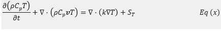
Accounts for heat conduction and convection in the fluid and solid regions of the heat exchanger.
4. Turbulence Model ( k-ω SST):
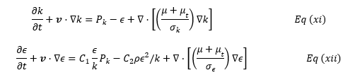
For accurate CFD modeling, turbulence is accounted for using a two-equation model k-ω SST, given by:
5. Nanofluid Thermophysical Properties:
![]()
The properties of nanofluids (thermal conductivity, viscosity, density, and specific heat) are modeled using empirical correlations:
• Effective Density:
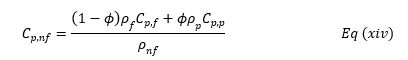
Effective Specific Heat Capacity:
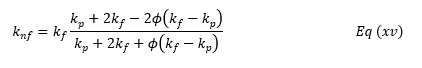
Effective Thermal Conductivity (Maxwell Model):
![]()
These equations govern the heat transfer and fluid dynamics within the shell-and-tube heat exchanger and are solved using CFD simulations in ANSYS.
Geometry Data
The geometry data for the shell-and-tube heat exchanger includes a tube length of 850 mm, with outer and inner tube diameters of 20 mm and 19 mm, respectively, and a tube pitch of 40 mm in a linear tube bundle arrangement. The shell has an outer diameter of 300 mm and an inner diameter of 298 mm, with a matching length of 850 mm. The baffle types being considered are Disc-and-Doughnut, Helical, and Double Segmental, with baffle spacings of 30 mm, 60 mm, and 90 mm. For the helical baffle, the angles used are 6°, 7°, and 8°. The inlet and outlet diameters are 50 mm, while the overall dimensions of the heat exchanger are 350 mm in diameter and 900 mm in length.
.png)
Table 4 Geometry Data from heat exchangers used in published work of Arsana and Wahyuono (2021).
Parametric Variation
Parametric variation is shown in following table.
.png)
Table 5 Parametric Variations
Cases to investigate in ANSYS
This setup generates 9 cases per fluid, accounting for each baffle type, spacing, and angle, providing a comprehensive investigation for the CFD simulations.
.png)
.png)
Table 6 Cases to investigate in ANSYS
Project Resources, Budget and Acquisition Plan
1. Project Resources
• Software: ANSYS CFD Software, Data Analysis Tools (MS Excel).
• Hardware: High-performance computing systems.
2. Budget
• Software Licenses: ANSYS CFD License and Data Analysis Tools (Student Version will be used which is freely available).
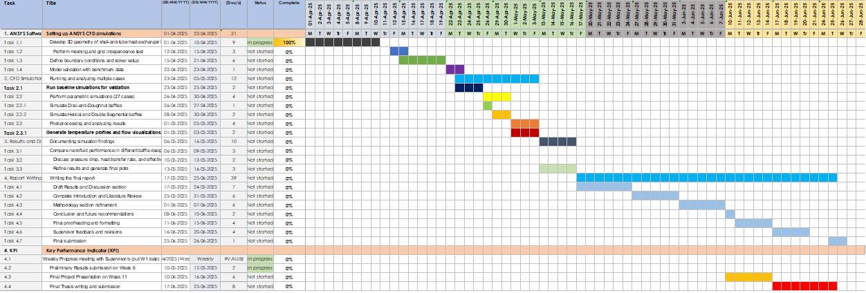
Gantt Chart
Chapter 4: Results and Discussions
Geometry Design
The shell-and-tube heat exchanger is designed with a linear tube bundle arrangement consisting of 49 tubes within the shell. The tube length is 850 mm, with an outer diameter of 20 mm and an inner diameter of 19 mm. The tube pitch is maintained at 40 mm to ensure adequate spacing for fluid flow and heat transfer. The shell has an outer diameter of 300 mm and an inner diameter of 298 mm, matching the tube length of 850 mm. Figure 4 illustrates the arrangement of the tubes within the shell, providing an optimized configuration for efficient thermal performance.
.png)
Figure 4 Arrangment of tubes in Shell (Total: 49 tubes)
Results to Be Obtained
The results of this study will focus on several critical aspects of thermal performance, pressure drop, and baffle arrangement effectiveness in shell-and-tube heat exchangers using nanofluids.
1. Thermal Performance Analysis
• Comparison of Temperature Differences: This analysis will evaluate the temperature differences across the different nanofluids (Al?O?–H?O, SiO?–H?O, TiO?–H?O) to determine which fluid provides the most efficient heat transfer.
• Heat Transfer Rates and Effectiveness: The heat transfer rates and effectiveness for each nanofluid will be quantified to assess their thermal performance under various operating conditions.
2. Pressure Drop Analysis
• Measurement of Pressure Drops: Pressure drops across the shell and tube sections for each nanofluid will be measured, providing insights into the resistance encountered by the fluid flow.
• Influence of Baffle Arrangements: The analysis will also assess how different baffle arrangements impact pressure loss, which is essential for understanding the overall efficiency of the heat exchanger.
3. Effectiveness of Baffle Arrangements
• Comparison of Heat Transfer Efficiency: The efficiency of heat transfer will be compared across different baffle types, specifically Disc and Doughnut, Helical, and Double Segmental, to identify the most effective design for enhancing performance.
• Variations in Baffle Angles and Distances: The study will analyze how variations in baffle angles and distances influence overall performance, providing data that could inform optimal design choices.
Result Validation Method
The result validation method will involve a comparison with the published data from Arsana and Wahyuono (2021). This approach entails evaluating the CFD simulation results for temperature distribution, pressure drops, and overall heat exchanger effectiveness against the experimental and computational results presented in their study. Key performance indicators, including heat transfer rates, pressure drop values, and temperature gradients, will be meticulously matched with those reported in the referenced work to ensure the accuracy and reliability of the CFD model.
Result Analysis Method
.png)
Table 7 Result Analysis Method
Analysis Aspect Details
Nanofluid Performance Compare the thermal performance of different nanofluids (Al?O?–H?O, SiO?–H?O, TiO?–H?O) to determine which provides the highest heat transfer efficiency and lowest pressure drop.
Baffle Arrangement Impact Assess how different baffle types and configurations influence heat transfer and pressure drop. Evaluate the performance of Disc and Doughnut baffles, Helical baffles, and Double Segmental baffles.
Chapter 5: Conclusions and Reccomendations
Concluding Remarks
The investigation into the use of nanofluids, combined with optimized baffle configurations, reveals a significant potential to enhance heat transfer in shell-and-tube heat exchangers. By leveraging the unique properties of nanofluids, such as their improved thermal conductivity, this project aims to address inefficiencies in traditional heat exchange processes. Additionally, CFD simulations will play a crucial role in predicting thermal performance and validating the effectiveness of these design modifications. Through accurate modeling, the project seeks to establish a reliable framework for evaluating the benefits of integrating nanofluids and innovative baffle designs.
However, further research is essential to tackle practical challenges that may arise, such as the stability of nanofluids, cost-effectiveness, and the optimization of baffle designs. Addressing these issues will be vital for making these advanced solutions feasible and practical for industrial applications, ultimately contributing to improved energy efficiency and performance in heat exchanger systems.
References
1. Arsana, I.M., Muhimmah, L.C., Nugroho, G. and Wahyuono, R.A., 2021. Enhanced heat transfer effectiveness using low concentration SiO2-TiO2 core-shell nanofluid in a water/ethylene glycol mixture. Journal of Engineering Physics and Thermos physics, 94(2), pp.439-446.
2. Rusu, M.M., Wahyuono, R.A., Fort, C.I., Dellith, A., Dellith, J., Ignaszak, A., Vulpoi, A., Danciu, V., Dietzek, B. and Baia, L., 2017. Impact of drying procedure on the morphology and structure of TiO2 xerogels and the performance of dye-sensitized solar cells. Journal of Sol-Gel Science and Technology, 81(3), pp.693-703.
3. Ebrahimnia-Bajestan, E., Moghadam, M.C., Niazmand, H., Daungthongsuk, W. and Wongwises, S., 2016. Experimental and numerical investigation of nanofluids heat transfer characteristics for application in solar heat exchangers. International Journal of Heat and Mass Transfer, 92, pp.1041-1052.
4. Davarnejad, R. and Kheiri, M., 2015. Numerical comparison of turbulent heat transfer and flow characteristics of SiO2/water nanofluid within helically corrugated tubes and plain tubes. International Journal of Engineering, Transaction B: Applications, 28, pp.1408-1414.
5. Duangthongsuk, W. and Wongwises, S., 2009. Measurement of temperature-dependent thermal conductivity and viscosity of TiO2-water nanofluids. Experimental Thermal and Fluid Science, 33, pp.706-714.
6. Barzegarian, R., Moraveji, M.K. and Aloueyan, A., 2016. Experimental investigation on heat transfer characteristics and pressure drops of BPHE (brazed plate heat exchanger) using TiO2-water nanofluid. Experimental Thermal and Fluid Science, 74, pp.11-18.
7. Azmi, W.H., Hamid, K.A., Mamat, R., Sharma, K.V. and Mohamad, M.S., 2016. Effects of working temperature on thermo-physical properties and forced convection heat transfer of TiO2 nanofluids in water-ethylene glycol mixture. Applied Thermal Engineering, 106, pp.1190-1199.
8. Reddy, M.C.S. and Rao, V.V., 2013. Experimental studies on thermal conductivity of blends of ethylene glycol-water-based TiO2 nanofluid. International Community Heat and Mass Transfer, 46, pp.31-36.
9. Bhanvase, B.A., Sarode, M.R., Putterwar, L.A., Abdullah, K.A., Deosarkar, M.P. and Sonawane, S.H., 2014. Intensification of convective heat transfer in water/ethylene glycol based nanofluids containing TiO2 nanoparticles. Chemical Engineering and Processing, 82, pp.123-131.
10. Hamid, K.A., Azmi, W.H., Mamat, R. and Sharma, K.V., 2016. Experimental investigation on heat transfer performance of TiO2 nanofluids in water-ethylene glycol mixture. International Community Heat and Mass Transfer, 73, pp.16-24.
11. Davarnejad, R. and Ardehali, R.M., 2014. Modeling of TiO2-water nanofluid effect on heat transfer and pressure drop. International Journal of Engineering, Transaction B: Applications, 27, pp.195-202.
12. Pirhayati, M., Akhavan-Behabadi, M.A. and Khayat, M., 2014. Convective heat transfer of oil-based nanofluid flow inside a circular tube. International Journal of Engineering, Transaction B: Applications, 27, pp.341-348.
13. Bhanuteja, S. and Azad, D. (2013). THERMAL PERFORMANCE AND FLOW ANALYSIS OF NANOFLUIDS IN A SHELL AND TUBE HEAT EXCHANGER. International Journal of Mechanical Engineering and Technology (IJMET), [online] 4(5). Available at: https://citeseerx.ist.psu.edu/document?repid=rep1&type=pdf&doi=776da8b2ac330ea65b0435c18c901d4aa60d0390 [Accessed 21 Aug. 2024].
14. Choi, S.U.S., Zhang, Z.G., Yu, W., Lockwood, F.E. and Grulke, E.A. (2001). Anomalous thermal conductivity enhancement in nanotube suspensions. Applied Physics Letters, 79(14), pp.2252–2254. Doi: HTTPs://doi.org/10.1063/1.1408272.
15. Farajollahi, B., Etemad, S.Gh. and Hojjat, M. (2010). Heat transfer of nanofluids in a shell and tube heat exchanger. International Journal of Heat and Mass Transfer, 53(1-3), pp.12–17. Doi: HTTPs://doi.org/10.1016/j.ijheatmasstransfer.2009.10.019.
16. Arsana and Ruri Agung Wahyuono (2021). Nanofluid-Enhancing Shell and Tube Heat Exchanger Effectiveness with Modified Baffle Architecture. Intech Open eBooks. Doi: HTTPs://doi.org/10.5772/intechopen.96996.
17. Kücük, H., Ünverdi, M. and Senan Y?lmaz, M. (2019). Experimental investigation of shell side heat transfer and pressure drop in a mini-channel shell and tube heat exchanger. International Journal of Heat and Mass Transfer, 143, p.118493. Doi: HTTPs://doi.org/10.1016/j.ijheatmasstransfer.2019.118493.
18. Li, H., Li, Y., Huang, B. and Xu, T. (2020). Numerical Investigation on the Optimum Thermal Design of the Shape and Geometric Parameters of Microchannel Heat Exchangers with Cavities. Micromachines, 11(8), p.721. Doi: HTTPs://doi.org/10.3390/mi11080721.
19. Mapa, L. and Mazhar, S. (2018). Session B-T4-4 HEAT TRANSFER IN MINI HEAT EXCHANGER USING NANOFLUIDS. [online] Available at: http://ilin.asee.org/Conference2005papers/P149.pdf [Accessed 21 Aug. 2024].
20. Masuda, Ebata, Teramae and Hishinuma (2014). H. Masuda, A. Ebata, K. Teramae and N. Hishinuma, ‘Alteration of Thermal Conductivity and Viscosity of Liquid by Dispersing Ultra-Fine Particles,’ Netsu Bussei, Vol. 7, No. 4, 1993, pp. 227-233. - References - Scientific Research Publishing. [online] Scirp.org. Available at: https://www.scirp.org/reference/referencespapers?referenceid=1073238 [Accessed 21 Aug. 2024].
21. Mohammad Hemmat Esfe, Yan, W.-M., Somchai Wongwises, Sarraf, M., Davood Toghraie and Mahidzal Dahari (2016). Estimation of thermal conductivity of Al2O3/water (40%)–ethylene glycol (60%) by artificial neural network and correlation using experimental data. 74, pp.125–128. Doi: HTTPs://doi.org/10.1016/j.icheatmasstransfer.2016.02.002.
22. Mohammed, H.A., Bhaskaran, G., Shuaib, N.H. and Saidur, R. (2011). Numerical study of heat transfer enhancement of counter nanofluids flow in rectangular microchannel heat exchanger. Superlattices and Microstructures, 50(3), pp.215–233. Doi: HTTPs://doi.org/10.1016/j.spmi.2011.06.003.
23. Rajalingam A and Chakraborty, S. (2023). Microchannel heat sink with microstructure wall — A critical study on fluid flow and heat transfer characteristics. Thermal Science and Engineering Progress, 38, pp.101613–101613. Doi: HTTPs://doi.org/10.1016/j.tsep.2022.101613.
24. Wajahat Ahmed Khan, Shaikh, K., Nawaz, R., Salim Newaz Kazi and Mohd (2024). Enhancement of heat transfer with nanofluids and its applications in heat exchangers. Advances in heat transfer, pp.101–128. Doi: HTTPs://doi.org/10.1016/bs.aiht.2024.05.001.
25. Arveng 2015, Basics of Shell & Tube Heat Exchangers, Arveng Training & Engineering.
26. Australian PV Institute. (2022). Queensland: The solar state. Retrieved from https://pv-map.apvi.org.au/state/QLD
27. Cui, W, Si, T, Li, X, Li, X, Lu, L, Ma, T & Wang, Q 2022, ‘Heat transfer analysis of phase change material composited with metal foam-fin hybrid structure in inclination container by numerical simulation and artificial neural network’, Energy Reports, vol. 8, Elsevier BV, pp. 10203–10218.
28. Faden, M, König-Haagen, A & Dieter Brüggemann 2019, ‘An Optimum Enthalpy Approach for Melting and Solidification with Volume Change’, Energies, vol. 12,
Multidisciplinary Digital Publishing Institute, no. 5, pp. 868–868.
29. Fryer, M 2021, Fouling in Heat Exchangers: Learn Causes, Detection, and Prevention, Central States Industrial.
30. Hou, TK, Kazi, SN, Mahat, AB, Teng, CB, Al-Shamma’a, A & Shaw, A 2017, Industrial Heat Exchanger: Operation and Maintenance to Minimize Fouling and Corrosion, www.intechopen.com, IntechOpen.
31. Li, M, Hicham Chaouki, Robert, J-L, Ziegler, D, Martin, D & Fafard, M 2018, ‘Numerical simulation of Stefan problem with ensuing melt flow through XFEM/level set method’, Finite Elements in Analysis and Design, vol. 148, Elsevier BV, pp. 13–26.
32. M., M 2011, ‘Fouling of Heat Transfer Surfaces’, Heat Transfer - Theoretical Analysis, Experimental Investigations and Industrial Systems.
33. Queensland Government. (2021). Solar power and battery storage. Retrieved from https://www.qld.gov.au/environment/climate/climate-change/renewable-energy/solar
34. Congedo, P. M., Colangelo, G., & Starace, G. (2012). CFD simulations of horizontal ground heat exchangers: A comparison among different configurations. Applied Thermal Engineering, 33-34, 24–32. https://doi.org/10.1016/j.applthermaleng.2011.09.005
35. Edreis, E., & Petrov, A. (2020). Types of heat exchangers in industry, their advantages and disadvantages, and the study of their parameters. IOP Conference Series: Materials Science and Engineering, 963(963), 012027. https://doi.org/10.1088/1757-899x/963/1/012027
36. EPCM Holdings. (2020, August 12). DESIGN OF SHELL AND TUBE HEAT EXCHANGER. EPCM Holdings. https://epcmholdings.com/design-of-shell-and-tube-heat-exchanger/
37. Faden, M., König-Haagen, A., Höhlein, S., & Dieter Brüggemann. (2017). An implicit algorithm for melting and settling of phase change material inside macrocapsules. International Journal of Heat and Mass Transfer, 117, 757–767. https://doi.org/10.1016/j.ijheatmasstransfer.2017.10.033
38. Perera, N., Perera, N., Flynn, D., & Hasan, R. (2023). Heat transfer and fluid flow characteristics of the passive method in double tube heat exchangers: A critical review. International Journal of Thermofluids, 17, 100282–100282. https://doi.org/10.1016/j.ijft.2023.100282
Fill the form to continue reading
Would you like to schedule a callback?
Send us a message and we will get back to you


Highlights
Earn While You Learn With Us
Confidentiality Agreement
Money Back Guarantee
Live Expert Sessions
550+ Ph.D Experts
21 Step Quality Check
100% Quality
24*7 Live Help
On Time Delivery
Plagiarism-Free

 81 Isla Avenue Glenroy, Mel, VIC, 3046 AU